changable dash cluster colour mod [work in progress]

rockit

Leaving Skid Marks
Location
SA
First Name
Robert
Drive
2000 Legnum
hi all, a little project im woriking on at the moment:
has been pretty much based on the guide on here on replacing the dash cluster needle LEDS, but up another level.

basically replacing the CCFL tube that backlights the dash cluster with some RGB LEDs so that the colour can be changed as my mood desires..

I have a stack of RGB LEDs wired up with each colour to its own variable resistor so taht i can tune the colour by adjusting each colour components resistor..

will also be doing the same with the dial needles (except on their own circuit so their colour can be different)

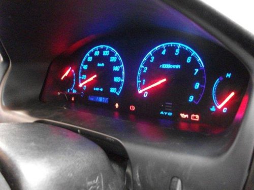
heres how its turning out so far:
yellow:
22062011_002.jpg

White (think i set the red up a little high, hence the pink bleeding through)
22062011.jpg

red
22062011_004.jpg

purple
22062011_006.jpg

blue
22062011_005.jpg

and the breadboard setup for green..
22062011_007.jpg


what still needs to be done:

need to work out the right number of LEDs to use so its not insanely bright, also need to work out where to place them so its not bright at the top but dim at the bottom etc.

need to make up some PCBs to fit into the dash cluster to make it neater and permanant.

Also need to make a external panel to mount somewhere where i can put a few small dials so i can adjust the colour easily, will also include a switch that automatically switches the LEDs to a setting where its close to the stock lighting (im not sure about the legality of modifying the dash panel)..

need to work out the current circuit paths so i can wire it into the dash cluster properly (just running off my computer power supply at the moment)

need to put the RGB LEDS into the dial needles and wire them up.


what im thinking of doing in the future:

changing it from resistor controlled to PWM using some microcontrollers.

using the microcontroller, setup some other effects ie make the fuel gauge nedle get redder the less petrol is in the tank until it gets critical then make it flash or somehitng,
make the rev-o-meter (whats the proper name??) go red when you get into the red zone etc just little things like that..

also want to modify a mobile phone screen so that i can have a small panel in the middle of the dash cluster that i can program to display what i want (fuel usage etc, similar as to what is in the current model lancers) (probably wont get done as i believe phone screens are tricky to get working by anything other than the phone that they are intended for!, but as an alternative i might try a cheap 3" screen from Ebay with normal inputs)
 

hozza

Leaving Skid Marks
Location
Queensland
First Name
Nathan
Drive
97 COTY manual legnum.(gone)
96 GTO MR
S13 silvia
bit of work there but looks cool.
to stop the bright patches you can paint the top of the leds with whiteout or something to help spread the light.
I think changing it to digital would be easier and more reliable.
but i am assuming the inputs into the fuel and tacho meter are analog so will need to a bit of work with some IC's.
Then getting them to dim is a whole other problem.
You could cheat and use a PLC but that would get quite expensive very quickly.
 

rockit

Leaving Skid Marks
Location
SA
First Name
Robert
Drive
2000 Legnum
looks goos mate..nice nailpolish as well ;)

thats not nailpolish... its whats left of my thumbnail after i smashed it with a hammer...


i have already got a diffuser in there above the leds (sheet of frosted transparent paper) .. i think i will have to spread the LEDS or angle them out more, as the CCFL they are replacing is very omnidirectional, wheras the LEDs only have a 20 or 30 degree angle, so more focused..


was jsut working out the hardware side of it at the moment, im definitly going to go digital once i work out which ICs to use.

i think PLCs are out, just too expensive

the ICs i have my eye on are somethign liek $1.4 each and dont require any external programming equipment, so quite cheap really.. just not sure if they will be up to doing some of the more complex stuff..

yeah the tacho/fuel stuff will probably be analogue, but the ICs im looking at have built in 7 bit ADC on a few pins, which gives 128 steps so should be plenty to get accurate enough reading for what i want to do..
 

hozza

Leaving Skid Marks
Location
Queensland
First Name
Nathan
Drive
97 COTY manual legnum.(gone)
96 GTO MR
S13 silvia
i have already got a diffuser in there above the leds (sheet of frosted transparent paper) .. i think i will have to spread the LEDS or angle them out more, as the CCFL they are replacing is very omnidirectional, wheras the LEDs only have a 20 or 30 degree angle, so more focused..
yeah thatll do it.

sounds like you all over it. pretty cool idea.
 

Lasiorhinus

Leaving Skid Marks
Lifetime Member
Location
Darwin
First Name
Stephen
Drive
White FL Legnum
Another way to get the tacho readings in an already digital format is from the ECU, either directly or via EvoScan. This would also work for the speedometer, which you could also colour-code to different speed ranges.

Fuel quantity is a tricky one. It might be workable to have the gauge needle itself move a small brush over some sequential contacts, in effect using the needle position to determine the colour.
 
G

Guest

Unregistered
i did it in blue to a few now really looks good
 

Attachments

  • DSCF1095.jpg
    DSCF1095.jpg
    48.5 KB · Views: 214
  • DSCF1100.jpg
    DSCF1100.jpg
    44.6 KB · Views: 216

rockit

Leaving Skid Marks
Location
SA
First Name
Robert
Drive
2000 Legnum
i did it in blue to a few now really looks good

out of curiosity, have you tried scratching the red layer off from under the tacho so it doesnt go purple? (not that the purple looks too bad anyway) but on mine some of the coolour combos dont work well with the red layer..
 
G

Guest

Unregistered
no you cant,brad wanted me to do it on his Facelift NA V6 i built him(bradc) and we looked but the red is printed on it,and if you scratch it it damages the clear and wont reflect nicely, i ment to do a write up here ages ago on how to do the led conversion,its so easy as,but i dont get pc time like i get wife time lol,if you have a chat,live video or something i can go thru the process with someone and then they can write up lol
 

Taylor

Leaving Skid Marks
Location
New Zealand
First Name
Taylor
Drive
1998 Galant VR4
thats not nailpolish... its whats left of my thumbnail after i smashed it with a hammer...


i have already got a diffuser in there above the leds (sheet of frosted transparent paper) .. i think i will have to spread the LEDS or angle them out more, as the CCFL they are replacing is very omnidirectional, wheras the LEDs only have a 20 or 30 degree angle, so more focused..


was jsut working out the hardware side of it at the moment, im definitly going to go digital once i work out which ICs to use.

i think PLCs are out, just too expensive

the ICs i have my eye on are somethign liek $1.4 each and dont require any external programming equipment, so quite cheap really.. just not sure if they will be up to doing some of the more complex stuff..

yeah the tacho/fuel stuff will probably be analogue, but the ICs im looking at have built in 7 bit ADC on a few pins, which gives 128 steps so should be plenty to get accurate enough reading for what i want to do..

Have a look at the TI launchpad. $3 for a complete development kit, once its programmed it only needs VCC and gnd, and the reset pin bought high. Verry powerful yet easy IDE 16bit processor
 

rockit

Leaving Skid Marks
Location
SA
First Name
Robert
Drive
2000 Legnum
will look into that, looks almost worth it just for the hardware and the 2 microcontrollers taht come with it....

having a discussion with my brother about which microcontrollers to use..

basically have decided that I will use 1 microcontroller with a I2C bus to 1 or 2 16 channel LED PWM driver modules..

most the microcontrollers themselves only have a handfull of hardware PWM channels avaliable, and then had to simulate PWM using code rather than hardware which i think would overtax the processor for anymore than a few LEDS. (also made doing anything else like reading in tacho readings etc difficult as any commands would interrupt the PWM driving)..

anyway.. i think im going with picaxe microcontrollers for $4 each and 2x LED drivers for $2each.. will require minimal external components (transistors and resistors pretty much all thats needed)..

just making up some basic PCBs at the moment, while I wait for teh microcontrollers and LED drivers to get here then i can start tinkering with some more complex stuff!
 

Taylor

Leaving Skid Marks
Location
New Zealand
First Name
Taylor
Drive
1998 Galant VR4
Picaxe? NOOOOOOOOOOOOO

TWI(i2c) is a good way to go, just a bit of a mind fuck to get your head around the code
 

rockit

Leaving Skid Marks
Location
SA
First Name
Robert
Drive
2000 Legnum
well bought one of those launchpad boards.. for $4.3 delivered cant really go wrong!

was going to go with picaxe purely for simplicity and ease of use.. programming a picaxe to do what i want looks like a very simple program.. but looks like this launchpad might be more complex..
 

Taylor

Leaving Skid Marks
Location
New Zealand
First Name
Taylor
Drive
1998 Galant VR4
It is indeed more complex but a hell of a lot more powerful. For what you are doing will be perfect as the chip uses a standard dual in line package prototyping and pcb making will cake. Picaxe i was using when i was 15, although the step up to c is a big one from basic, it is worthwhile, whats the point of undertaking on something like this if you cant learn along the way haha.

The TI stiff is unbelievably cheap, and I kid you not you will see it by weeks end.
 
Top Bottom