NSW Fl0w's Leggy From hell.

Fl0w

Idling at the Lights
Location
Australia
First Name
Kalven
Drive
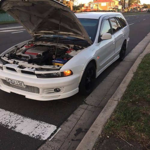
1998 Mitsubishi Legnum.
2010 Kawasaki ninja 250cc
1996 BMW 318I.
So decided I wanted a wagon AWD for snow this year.
Always loved sleeper wagons, have in the past owned multiple hatch sleepers from 626 turbo's to vl wagon turbos.

I'm a mechanic by trade so nothing usually fazes me ha.

Choices where basically Legnum or stagea in my price bracket, I loath Nissan with a passion and love EVO's so Leggy it was.

Bought the car with 10 minutes worth of clutch left in it (Literally had to flat tow it 100 metres to my driveway from finally kicking it on the way home)

Chucked a exedy HD clutch in it over the weekend. Went to drive away and engine stalls out... HUGE over fueling issue black smoke could literally smell the fuel.

We assumed it was low fuel or bad fuel, so filled it up with 98 after it sitting for a couple of days and it came good for a little while.

Happened to me once or twice after that, Ended up replacing the positive battery terminal since it was buggered.

Came good for like 2 months after that with 0 hickups. Then BAM! out of nowhere missfires in my face again in Canterbury like an hour and a half away from home.

Left it for the night hoping it would come good which it did not. Ended up paying for a tow truck to work.

Tested coils and thought I'd found a buggered coilpack so bought some second hand coils and she came good for a day again! Drove her home with 0 hickups and she was going fine.
Next morning decide to take her to work 100 metres down the road missfires again lol.


Unplugged MAF while missing and found if you blip the revs up she'll come good and stop missfiring.
Checked for codes and got no codes, Ripped plugs out today all 6 are fouled, but that's not surprise since it's been over fueling this whole time.

Leads are within spec, 681, 658, 565. NGK 0.9's so they shouldn't be an issue.


So at this point I'm thinking Fuel pump, MAF, TPS, etc. Probably going to have to fork out for a 1.3u cable and set up evoscan on my laptop -_-.

Cars spent more time dead on my driveway than it has being driven and it's starting to do my head in lol.
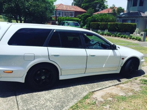
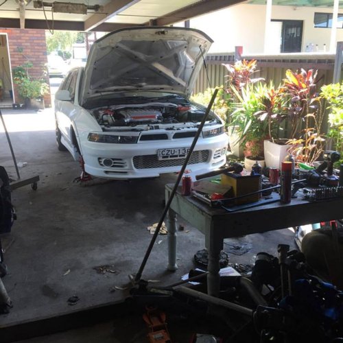
Uploaded some photo's just to show you at least it looks pretty ;) ha.

On top of the other issues, dude before me was a spaz.
Vac lines deterioated, Wiring nightmare on footwell from ripped out HIDS, Boost gauge wasn't even connected.
Rear diff mounts are completely shot, NSF balljoints are rooted from him replacing a control arm by himself, ALSO he managed to not even do any of the bolts up correctly leaving me almost losing a control arm while driving. Luckily I managed to find that while Doing clutch before it would of actually been an issue.

So yeah, here's my leggy that's basically sat in my driveway for 3 or 4 months now -_-

12715383_1297511620265821_9194684782833456134_n.jpg
12651255_1292017567481893_7886398069601172185_n.jpg
1614297_1269085269775123_1230693455905497648_o.jpg
581895_1277353588948291_3745069401614096448_n.jpg
 

mookers

puri puri
Location
Frankston, Melbourne, VIC
First Name
Derek
Drive
CL9 Accord Euro Lux, GE Jazz VTi, Evil Supervillain Chair, Homemade Portable Square Drumkit
Welcome aboard, Kalven. Hopefully some of the links below will assist you in getting your car sorted!

Unclepaulie's infamous welcome template, version 15.13e

Stuff you need to know:
- Forum rules

Stuff that could save your life:
Do not buy aftermarket suspension parts, especially Lower Control Arms (LCAs)

- This is what happens if you don't replace your control arms
- Recall check using your chassis number

Useful threads:
- INDEX - Look here FIRST
- Guide to Galant & Legnum common problems
- The most important thread on the forum. MUST READ
- Staged Upgrades
- Legnum/Galant Production Info

Posting new threads is restricted by default. For full access you need to be a Premium Member ($15 a year):
- Upgrading your account

Please read before selling anything on this site:
- Rules for posting in the classifieds
 

GMan

1 AYC Bar
Location
NSW
First Name
Jet
Drive
2000 Mitsubishi Galant VR-4
Welcome to the forum -- sorry to hear about your problems :(
 

Size1

Leaving Skid Marks
Location
N.S.W
First Name
Simon
Drive
00 legnum vr4
Welcome Kalven i am sure you will sort it out the issues and finally enjoy the car for what it really is.
 

Fl0w

Idling at the Lights
Location
Australia
First Name
Kalven
Drive
1998 Mitsubishi Legnum.
2010 Kawasaki ninja 250cc
1996 BMW 318I.
I'm in need of a 1.3u cable more than anything.

If I can look at live data and have a workshop manual handy I'll be golden ha.
 

Tony_T

Leaving Skid Marks
Location
Hamilton New Zealand
First Name
Tony
Drive
Legnum VR-4 1997
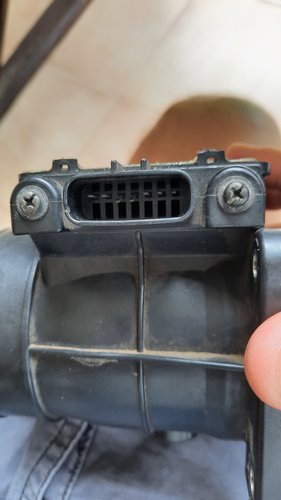
When it plays up again, unplug the MAF. If it now runs reasonably OK I have a thread somewhere on repairing the MAF: it's quite easy.
 

Fl0w

Idling at the Lights
Location
Australia
First Name
Kalven
Drive
1998 Mitsubishi Legnum.
2010 Kawasaki ninja 250cc
1996 BMW 318I.
Yeah it runs without maf plugged in.
Just waiting on cable to check frequency then will replace.

Is that just cleaning?
 

Tony_T

Leaving Skid Marks
Location
Hamilton New Zealand
First Name
Tony
Drive
Legnum VR-4 1997
No, don't try to clean it, you may damage the sensor wires. There's solder joints that crack on the circuit board due to thermal stresses. Resoldering the joints will fix it, the hardest part is getting the plastic lid off without breaking any of the four little tabs that hold it on .... but that's what silicone sealant is for: holding it back on when you do break them! Search for my posts, there should be my detailed instructions somewhere on this forum, if not I'll try to find my original text and paste it back on here. Let me know as I can't remember for sure if I posted it or sent it to someone in a PM.
BTW a replacement second-hand MAF would likely suffer from the same problem within a short time so it's better to fix the one you already have.
I had the problem with one of mine and as I'm an electronics tech I was determined to find and fix the cause once I found out it was the MAF that was causing the car to play up and my repaired one is still going fine.
 

Tony_T

Leaving Skid Marks
Location
Hamilton New Zealand
First Name
Tony
Drive
Legnum VR-4 1997
Apologies, I found it was in a PM so here it is:

The hardest part of the repair is getting the top lid off without breaking any of the four little plastic tabs which hold it on. In my case it seemed that there could have been a bit of silicone sealant also keeping the lid on which made it harder so I ended up breaking two of the tabs and having to improvise some clips to take their place. So, remove the MAF from the car and if you like, dismantle it from the plastic airway parts to make it easier to handle. Then remove the lid. Under the lid you'll see a metal shield which is held in place by springy tabs. Just ease the shield out, try not to bend it so it will fit back nicely later.

NOTE: the purpose of the shield is to prevent any radio frequency signals nearby from affecting the operation of the MAF. Test at idle with it removed but DO NOT take the car onto the road without it in place: I do not accept responsibility for any crashes caused by sudden changes to the car's operation while driving due to some nearby radio emission e.g. your cellphone!!!!!

Our MAF works by the incoming air, which has had turbulence caused by the special inlet and shaping, passing over two heated wires causing their temperature to vary. As with most metals the electrical resistance of these wires is temperature dependent so we have a variation of resistance in response to the airflow. To allow this resistance change to be measured accurately the current which flows through the wires to heat them must be carefully regulated. This is accomplished by having a precision resistor in series with each wire, the voltage which appears across this resistor is compared with a reference voltage in some simple electronics and the resulting error signal is used as feedback to the current control transistors. This means that when the car is switched on these resistors also heat slightly due to the current flowing through them, and when the car is switched off again they cool. As with most things they expand and contract slightly with this heating and cooling. They are soldered to copper tracks on a fibreglass based circuit board which has a different amount of thermal variation and this causes stress to be applied to the solder joints at each end of these resistors, eventually causing the solder to crystallize and become an intermittent connection which is very susceptible to vibration. In my case the car would often idle but when any throttle was applied the vibration caused the contact to make and break rapidly giving extra pulses from the MAF to the ECU. The ECU saw this as heaps more airflow and ramped up the fuel to the point where the mixture would not ignite stopping the engine and producing rather a lot of black smoke occasionally.

The repair:

I'm assuming you or someone you'll get to do this for you is confident with soldering of electronic components:

Locate the two larger resistors which are flat rectangular items on the circuit board towards the top right of the board if the socket which connects to the car loom is on your left. Mine had the value 6R2 written on them, I expect all MAF's will have the same value resistors, it could be written 6E2 by some manufacturers. Using a small soldering iron somewhere around 30 to 50 watts power and preferably temperature controlled carefully melt the solder on both ends of one of these resistors and lift it away from the PC board. A pair of fine tweezers may be helpful but don't damage the resistor. You may have to keep heating the ends alternately a few times to get it off (don't force it) unless you have one of the special soldering tools which heats both ends at once.

Don't do both resistors at once as all resistors have some production spread of actual resistance and this has been accurately compensated for at the factory (you'll see some tubular resistors on stand-off legs which have been chosen for exact calibration) so you don't want to mix them up.

Once it is removed, use the iron and some fresh electronics grade resin cored solder (preferably 60/40 leaded not lead-free as it cracks too easily) to reflow and clean the lands on the PCB where the resistor attaches. Then do likewise with the terminations on the actual resistor. When fully satisfied that all is clean and good to go, solder one end of the resistor back onto the PCB, leaving the resistor sticking up at a small angle so the other end is clear of its land on the board (if you're not too familiar with these things, they're not directional so can face either way). Now take a piece of scrap automotive electrical wire and strip it down to get some fairly thin single strands of copper and cut a strand about 5 or 6 mm long. Solder one end of this flat to the free land on the PCB and then curve the other end around to meet the resistor end flat-on. Now solder it. This provides a bit of 'give' by movement of the wire for the expansion and contraction so should help to prevent the problem from happening again. (I didn't do this when I fixed mine, I just soldered them back as they had been on the board and thought of this idea later so I will do it sometime).

Repeat for the second resistor.

Don't be tempted to just reflow the solder on the resistors in place: you won't get to the solder under them and it will be a very short term fix if it fixes it at all.

When you're happy that everything is connected correctly (it's possibly worth gently pulling on the curved wires to be sure they're really soldered properly) then refit the MAF to the car and test with the car stationary and tapping on the circuit board (not too hard that you break something though) with something insulating like a plastic pen to see that there's no change in engine operation at higher revs due to some other problem. All going well, fit the shield in place and go for a test drive (it won't pop out if you got it out without bending the metal fingers). If it passes the drive test then refit the plastic cover, putting some silicone sealant on if you wish (that may also hold it OK if you broke some tabs!) but use neutral cure silicone not RTV as RTV has an acid solvent which will corrode electronics.

If anyone would like to add this to one of the info threads, please feel free to do so if it hasn't already been done (I can't see those threads).
 

Size1

Leaving Skid Marks
Location
N.S.W
First Name
Simon
Drive
00 legnum vr4
Tony T i think you should do a write up on this for the guides sections so if someone searches for it., it can be found easily.(y)
 

Tony_T

Leaving Skid Marks
Location
Hamilton New Zealand
First Name
Tony
Drive
Legnum VR-4 1997
I'm not sure if I can do that as I'm not a paid member. If you would like to copy and paste the above to one of those threads, please feel free to do so with my blessing. Please don't modify it in any way though.
 

Brenton

Leaving Skid Marks
Location
Port Lincoln. South Australia
First Name
Brenton
Drive
97 PFL legnum
Apologies, I found it was in a PM so here it is:

The hardest part of the repair is getting the top lid off without breaking any of the four little plastic tabs which hold it on. In my case it seemed that there could have been a bit of silicone sealant also keeping the lid on which made it harder so I ended up breaking two of the tabs and having to improvise some clips to take their place. So, remove the MAF from the car and if you like, dismantle it from the plastic airway parts to make it easier to handle. Then remove the lid. Under the lid you'll see a metal shield which is held in place by springy tabs. Just ease the shield out, try not to bend it so it will fit back nicely later.

NOTE: the purpose of the shield is to prevent any radio frequency signals nearby from affecting the operation of the MAF. Test at idle with it removed but DO NOT take the car onto the road without it in place: I do not accept responsibility for any crashes caused by sudden changes to the car's operation while driving due to some nearby radio emission e.g. your cellphone!!!!!

Our MAF works by the incoming air, which has had turbulence caused by the special inlet and shaping, passing over two heated wires causing their temperature to vary. As with most metals the electrical resistance of these wires is temperature dependent so we have a variation of resistance in response to the airflow. To allow this resistance change to be measured accurately the current which flows through the wires to heat them must be carefully regulated. This is accomplished by having a precision resistor in series with each wire, the voltage which appears across this resistor is compared with a reference voltage in some simple electronics and the resulting error signal is used as feedback to the current control transistors. This means that when the car is switched on these resistors also heat slightly due to the current flowing through them, and when the car is switched off again they cool. As with most things they expand and contract slightly with this heating and cooling. They are soldered to copper tracks on a fibreglass based circuit board which has a different amount of thermal variation and this causes stress to be applied to the solder joints at each end of these resistors, eventually causing the solder to crystallize and become an intermittent connection which is very susceptible to vibration. In my case the car would often idle but when any throttle was applied the vibration caused the contact to make and break rapidly giving extra pulses from the MAF to the ECU. The ECU saw this as heaps more airflow and ramped up the fuel to the point where the mixture would not ignite stopping the engine and producing rather a lot of black smoke occasionally.

The repair:

I'm assuming you or someone you'll get to do this for you is confident with soldering of electronic components:

Locate the two larger resistors which are flat rectangular items on the circuit board towards the top right of the board if the socket which connects to the car loom is on your left. Mine had the value 6R2 written on them, I expect all MAF's will have the same value resistors, it could be written 6E2 by some manufacturers. Using a small soldering iron somewhere around 30 to 50 watts power and preferably temperature controlled carefully melt the solder on both ends of one of these resistors and lift it away from the PC board. A pair of fine tweezers may be helpful but don't damage the resistor. You may have to keep heating the ends alternately a few times to get it off (don't force it) unless you have one of the special soldering tools which heats both ends at once.

Don't do both resistors at once as all resistors have some production spread of actual resistance and this has been accurately compensated for at the factory (you'll see some tubular resistors on stand-off legs which have been chosen for exact calibration) so you don't want to mix them up.

Once it is removed, use the iron and some fresh electronics grade resin cored solder (preferably 60/40 leaded not lead-free as it cracks too easily) to reflow and clean the lands on the PCB where the resistor attaches. Then do likewise with the terminations on the actual resistor. When fully satisfied that all is clean and good to go, solder one end of the resistor back onto the PCB, leaving the resistor sticking up at a small angle so the other end is clear of its land on the board (if you're not too familiar with these things, they're not directional so can face either way). Now take a piece of scrap automotive electrical wire and strip it down to get some fairly thin single strands of copper and cut a strand about 5 or 6 mm long. Solder one end of this flat to the free land on the PCB and then curve the other end around to meet the resistor end flat-on. Now solder it. This provides a bit of 'give' by movement of the wire for the expansion and contraction so should help to prevent the problem from happening again. (I didn't do this when I fixed mine, I just soldered them back as they had been on the board and thought of this idea later so I will do it sometime).

Repeat for the second resistor.

Don't be tempted to just reflow the solder on the resistors in place: you won't get to the solder under them and it will be a very short term fix if it fixes it at all.

When you're happy that everything is connected correctly (it's possibly worth gently pulling on the curved wires to be sure they're really soldered properly) then refit the MAF to the car and test with the car stationary and tapping on the circuit board (not too hard that you break something though) with something insulating like a plastic pen to see that there's no change in engine operation at higher revs due to some other problem. All going well, fit the shield in place and go for a test drive (it won't pop out if you got it out without bending the metal fingers). If it passes the drive test then refit the plastic cover, putting some silicone sealant on if you wish (that may also hold it OK if you broke some tabs!) but use neutral cure silicone not RTV as RTV has an acid solvent which will corrode electronics.

If anyone would like to add this to one of the info threads, please feel free to do so if it hasn't already been done (I can't see those threads).
 

Brenton

Leaving Skid Marks
Location
Port Lincoln. South Australia
First Name
Brenton
Drive
97 PFL legnum
Did this recently ( well had someone do it for me) as I didn't feel confident soldering such intricate electronics, it works. After driving 200ks highway with it playing up, used an extra 15 litres fuel and filled my exhaust and varex with black soot. Has run perfectly since.
 

jungle

3 AYC Bars
Lifetime Member
Location
QLD
First Name
Simon
Drive
1 PFL & 1 FL Legnum
So quick one, you guys removed the board from the plastic housing. how,? Removing the 4 screws on the board and the 2 external that hold the loom connector?

20210119_085134.jpg
20210119_085142.jpg
 

BCX

Administrator
Moderator
Location
SA
First Name
Bill
Drive
2000 Galant Type-V
1997 MK Triton GLS [6G74 conversion]
2019 i30 N-Line
Our MAF works by the incoming air, which has had turbulence caused by the special inlet and shaping, passing over two heated wires causing their temperature to vary. As with most metals the electrical resistance of these wires is temperature dependent so we have a variation of resistance in response to the airflow.

Mitsubishi MAFs are Karmen Vortex type - uses a ultrasonic transmitter and receiver pair. Vortex creates turbulence and causes disruption to the ultrasonic wave.
 

Tony_T

Leaving Skid Marks
Location
Hamilton New Zealand
First Name
Tony
Drive
Legnum VR-4 1997
@BCX Not the ones in our Legnums. They use heated wires which vary in temperature and hence resistance with the turbulence not ultrasonics.

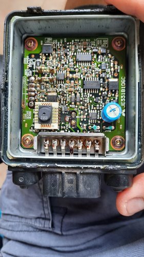
@jungle The repair is easily done without removing the board, in fact there would be no advantage to do so, the two resistors are visible in that excellent pic. one next to the connector which goes through the board on the left and the other a little above that, they're clearly marked 6R2 in that pic and there's nothing around them to obstruct access with any reasonable electronics type soldering iron. A small pair of tweezers may be of assistance in removing them.
 
Top Bottom