Boost solenoid plumbing

leebutts

1 AYC Bar
Location
New Zealand
First Name
Lee
Drive
2001 Golf GTI
So...

I've always been curious about the way my aftermarket solenoid was plumbed in by my tuner.

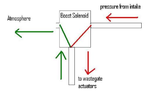
Behold my awesome diagram!!

The red line below shows the flow when the solenoid is off, the green when it's on.

boostsol.jpg


I'm trying to work out how to improve the boost curve as it looses 2 or 3 psi above 4500. I'm wondering if plumbing the current output (that goes to atmosphere in the diagram) back into the intake before the turbos will help.

Would the suction from the intake help to "pull" the wastegates closed?
I'm thinking maybe the wastegates are staying open/leaking due to the increased boost.
 
G

Guest

Unregistered
The factory one is plumbed back in, so it probably wouldn't hurt. You should still have the nipple there to attach a hose to.
 

leebutts

1 AYC Bar
Location
New Zealand
First Name
Lee
Drive
2001 Golf GTI
You should still have the nipple there to attach a hose to.

Nope, intake is all custom now but can add one in easy enough.

I guess my main question is - will suction on the wastegate actuator line "pull" the wastegate closed or not?
 

pu-11-me

and put an LSD in it
Location
NSW
First Name
Dawso
Drive
VW Touareg
Negative pressure (Vacuum) on that line will close the wastegate Lee, and anything over 7ish PSI actuator side of the solenoid will open it (Losing you boost)

Also, that is the worst diagram I have ever seen dude lol.... I'll check it out with you next time I see you :)
 
G

Guest

Unregistered
Just to clarify that, it wasn't the end of the hose connected to the BOV.. it was up the other end of the hose where it connected to the turbo outlets.
 

leebutts

1 AYC Bar
Location
New Zealand
First Name
Lee
Drive
2001 Golf GTI
Just to clarify that, it wasn't the end of the hose connected to the BOV.. it was up the other end of the hose where it connected to the turbo outlets.

Yeah, I've replaced the factory pipe going to the throttle so I had to remove and refit the hose then.

cheers

Lee
 

Kenneth

1 AYC Bar
Location
New Zealand
First Name
Kenneth
Drive
1999 Galant VR-4
To apply vacuum to the wastegates you would have to attach the "Atmosphere" solenoid port to just in front of one the turbo inlets, and the pressure inlet port will have to close.
So, the question is whether the valve connects pressure inlet with outlet, or wastegate with outlet. If the former, there will be no suction applied to the wastegates.

Is your EBC configurable by RPM point? If so, you might just need to increase the duty cycle (assuming duty cycle increase vents more to atmosphere) as RPM increases to hold boost.

Alternatively, the intake pressure has a very direct result on boost.
Turbos work on pressure ratio which means that the intake pressure is multiplied to get the outlet pressure.
Because of this, any restriction is also multiplied by the pressure ratio. As a result, if the turbo was currently running a 2.0 pressure ratio, a 1psi pressure drop at the intake results in a 2psi pressure drop on your gauge.

As your RPM and load increases, the amount of air you need to sustain a specific boost level also increases. If the intake is such that increasing the flow rate causes substantial pressure loss due to restriction, then you start loosing "boost" at the engine, despite your turbo still working at the same pressure ratio.


For example, (atmospheric pressure is ~14.7psi) if you loose 2.7psi through intake restriction to the turbo and the turbo is currently running a 2.0 pressure ratio:

14.7- 2.7 = 12 (absolute pressure at the turbo intake)
12 x 2 = 24 (absolute pressure on the turbo outlet)
24 - 14.7 = 9.3 (gauge pressure on turbo outlet.)

Now if you reduce the restriction by 1psi (to 1.7psi of restriction)

14.7 - 1.7 = 13 (absolute pressure at the turbo intake)
13 x 2 = 26 (absolute pressure at the turbo outlet)
26 - 14.7 = 11.3 (gauge pressure)
 
G

Guest

Unregistered
On your diagram you have your flow arrows marked incorrectly. On a three-port boost solenoid there is no back-flow path from the wastegate actuators to the atmosphere when the solenoid is in the energised 'on' state. The actuator line will simply be blocked off and the boost pressure will be diverted to the atmosphere.

When the solenoid is 'off' it will be in the NO (Normally Open) state and pass all pressure straight through to the actuators, opening the wastegates at a low boost. A spring returns it to this state.

In theory, boost pressure could be getting locked in the actuator lines keeping them pressurised and holding the wastegates slightly open but I'm not sure if in reality that is possible.

The problem could lie with a faulty solenoid or one of your wastegate actuator's could be bung or just not up to the boost levels that you are aiming for.

I'm also assuming that you don't have any boost leaks elsewhere in your system. It will be a process of elimination unfortunately and I'd start by taking the boost solenoid out of the equation.
 

leebutts

1 AYC Bar
Location
New Zealand
First Name
Lee
Drive
2001 Golf GTI
So, the question is whether the valve connects pressure inlet with outlet, or wastegate with outlet. If the former, there will be no suction applied to the wastegates.

I've checked the markings on the outside of the solenoid and it's set up to connect wastegates with outlet.

Is your EBC configurable by RPM point? If so, you might just need to increase the duty cycle (assuming duty cycle increase vents more to atmosphere) as RPM increases to hold boost.

It is, I could increase it a bit more. It's currently at 48% at 4750, rising to 100% at 6000.

The drop definitely could be caused by restriction in the intake, however I have no MAF and a 2" intake going to each turbo with a separate pod filter on each so I don't know how I can improve the flow other than getting bigger pod filters. There would be no point in increasing the intake size any larger than the turbo inlets - correct?
 

leebutts

1 AYC Bar
Location
New Zealand
First Name
Lee
Drive
2001 Golf GTI
On your diagram you have your flow arrows marked incorrectly. On a three-port boost solenoid there is no back-flow path from the wastegate actuators to the atmosphere when the solenoid is in the energised 'on' state. The actuator line will simply be blocked off and the boost pressure will be diverted to the atmosphere.

No, I've checked the markings on the outside of the solenoid and it has been plumbed "backwards".

e.g. where you would normally attach the 'in' line is actually the wastegate line, not the line coming from the intake. One output is atmosphere and the other has the line from the intake.

I'll go and take a picture if you don't believe me :)
 

Kenneth

1 AYC Bar
Location
New Zealand
First Name
Kenneth
Drive
1999 Galant VR-4
I've checked the markings on the outside of the solenoid and it's set up to connect wastegates with outlet.
Then you could connect it pre-turbo and see if it makes any difference.

It is, I could increase it a bit more. It's currently at 48% at 4750, rising to 100% at 6000.

The drop definitely could be caused by restriction in the intake, however I have no MAF and a 2" intake going to each turbo with a separate pod filter on each so I don't know how I can improve the flow other than getting bigger pod filters. There would be no point in increasing the intake size any larger than the turbo inlets - correct?

Greater pipe diameter will reduce the air speed pre-intake. This reduction in air speed at full load will result in a higher pressure pre-turbo. The question is at which pipe diameter the flow rate remains slow enough for this to not really matter.

What I would do is put a nipple on the pipe just before turbo entry and connect it to your boost gauge. (assuming you have a standalone one, if not borrow one). As you do a full load pull, you (probably your passenger) can monitor the gauge and see if it moves into the negative. If so, you have pressure loss.

A boost gauge isn't ideal for that test because it isn't sensitive enough, but if it does show negative pressure then you have substantial vacuum.
 
G

Guest

Unregistered
I'm sorry, you were actually correct... my brain hurts this morning. I'm getting the ports the wrong way around.

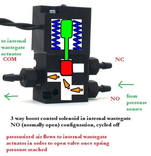
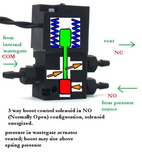
- COM (common) should be connected to the wastegate line
- NO (normally open) comes from your pressure source post-turbos
- NC (normally close) in your case is venting to atmosphere (which mine is actually doing too).

So... the line going to the wastegates will switch between accepting pressure when the solenoid is 'off' or being open to the atmosphere and venting pressure when the solenoid is 'on'.

The pressure lock was something that I remembered reading on Autospeed but had a look and can't find the article so not sure why they said it could happen but it must have been in a different type of configuration.

But your question remains, why are you loosing boost? Is the solenoid malfunctioning or leaking somehow and passing pressure to the wastegates when it should be withholding it? Or have your actuators become weak and can't hold the wastegates shut properly?

Many people have their solenoids with the NC port simply venting. What kind of boost levels are you aiming for out of interest?
 

leebutts

1 AYC Bar
Location
New Zealand
First Name
Lee
Drive
2001 Golf GTI
Many people have their solenoids with the NC port simply venting. What kind of boost levels are you aiming for out of interest?

I'd like to see what kind of power I can get from a flat 17psi curve. It currently makes 16/17 down low then falls off up top to 14/15ish. It's pretty bumpy however.

The next firmware release for my vi-pec should have closed loop boost control so hopefully that will help smooth it out more than the current RPM vs duty cycle table can.

Thanks for all your input guys, I'll let you know if I make any improvements.

cheers

Lee
 
G

Guest

Unregistered
I just found these pics that illustrate the solenoid operation really well and hopefully make amends for any confusion that I've caused. . :(

EDIT: Pics fixed now, must have been in my cache because they were showing up for me until I forced a refresh.

Thanks to RX7Club.com

Solenoid_open.jpg
Solenoid_closed.jpg
 
Top Bottom