You are using an out of date browser. It may not display this or other websites correctly.
You should upgrade or use an alternative browser.
You should upgrade or use an alternative browser.
Fuel gauge recalibrator project
- Thread starter Kaldek
- Start date
ersanalamin
Leaving Skid Marks
Now that I have a very accurately calibrated UTCOMP in the car, I have some interesting pictures to show you.
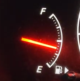
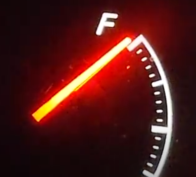
I noticed that the top half of the gauge for accuracy wasn't too far off. At 23 litres consumed, the gauge was slightly above the halfway mark - close to being accurate. But at ~29 litres consumed, it has dropped by a quarter of a tank reading. Six litres for a quarter of a tank!! My target calibration is one needle "notch" per every three litres, whereas here between halfway and one quarter, it has moved almost five notches. That should normally require a consumption of 15 litres - more than double what was actually consumed to make the needle drop this far.
Hi ed, which wire to tap on dash for utcomp fuel sensor? i like it. is utcomp read the remaining gas on tank accurately?
Kaldek
2 AYC Bars
- Location
- Melbourne
- First Name
- Ed
- Drive
- 2000 Legnum VR4 Manual, Ford Territory family runabout, BMW K1300R.
- Thread starter
- #63
The UTCOMP gauge works automatically - you just fill up the fuel tank and tell the UTCOMP that you have filled it. It's in the manual.Hi ed, which wire to tap on dash for utcomp fuel sensor? i like it. is utcomp read the remaining gas on tank accurately?
It's highly accurate, and is based on fuel injector constant. You don't need to connect to the car's fuel gauge.
Kaldek
2 AYC Bars
- Location
- Melbourne
- First Name
- Ed
- Drive
- 2000 Legnum VR4 Manual, Ford Territory family runabout, BMW K1300R.
- Thread starter
- #65
Well that's annoying. My 1kohm digital pot starts at 50 ohms resistance. I did the proper reading and found that that, yep, this family of digital potentiometers all start at 50 ohms. D'oh!
Looks like I'm back to the idea of driving the gauge using PWM switching.
Looks like I'm back to the idea of driving the gauge using PWM switching.
Kaldek
2 AYC Bars
- Location
- Melbourne
- First Name
- Ed
- Drive
- 2000 Legnum VR4 Manual, Ford Territory family runabout, BMW K1300R.
- Thread starter
- #66
Project on hold while I get my head around switching the ground side of the circuit using a transistor controlled by the Arduino.
This thread has become a stream of consciousness rather than instructions. It almost needs to get deleted and started again.
This thread has become a stream of consciousness rather than instructions. It almost needs to get deleted and started again.
- Location
- SA
- First Name
- Bill
- Drive
- 2000 Galant Type-V
1997 MK Triton GLS [6G74 conversion]
2019 i30 N-Line
Project on hold while I get my head around switching the ground side of the circuit using a transistor controlled by the Arduino.
Send me an email with your schematic and what you're trying to do.
Kaldek
2 AYC Bars
- Location
- Melbourne
- First Name
- Ed
- Drive
- 2000 Legnum VR4 Manual, Ford Territory family runabout, BMW K1300R.
- Thread starter
- #69
Well folks, time for an update. Yeah 2017 didn't happen but I've recently done a bunch of electrical stuff so I'm "in the zone".
Back in 2016 I did not realise that you can just run resistors in parallel to drop the resistance of a circuit. Duh. So, this means that I could use a digital pot to bring the circuit resistance down to the required ranges. We're talking bringing 50 ohms down to 4 ohms, which I'm not sure I can manage yet as I haven't even done the calculations.
Also as I said back in 2016, the PWM option is also possible. I want to try and avoid this though as I worry that the PWM might introduce noise into the car's electrical system.
Anyway, the first step I what I want to do is actually to measure the current passing through the fuel gauge circuit because I'm limited to about 30mA before the chips I'm using let the magic smoke out. That will actually define the limits of my proposed solutions.
Kaldek
2 AYC Bars
- Location
- Melbourne
- First Name
- Ed
- Drive
- 2000 Legnum VR4 Manual, Ford Territory family runabout, BMW K1300R.
- Thread starter
- #70
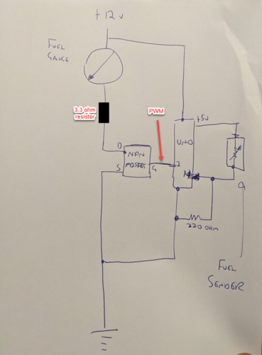
Actually, here's my prototype circuit idea. It's an Arduino (Uno) going Man-In-The-Middle and replacing the fuel sender circuit with an N-channel MOSFET rapidly switched on an off using Pulse Width Modulation (PWM). If the circuit is powered on permanently somehow, the 3.3 ohm resistor mimics the "Full" position on the fuel gauge (~4 ohms roughly).
At all other times, the Arduino is constantly reading the fuel level and based on this calibrated reading, it drives the pulse width modulation of the MOSFET on and off to average out the current that will drive the gauge to the desired position.
Calibration is a matter of filling up the car and resetting my UTCOMP to show 60 litres and then just basically driving it and noting the voltage readings at certain amounts of fuel consumed.
The fuel gauge has 21 segments between F and E but due to the way the tank has two fuel senders in series (which is part of the reason the fuel gauge is so inaccurate), and we're less concerned about a full fuel gauge than a nearly empty one, I will probably have to split the measurements so I only take one measurement every 2.7 litres for the first half of the tank and then start to take more measurements for the next/lower half, like one every 1.3 litres.
Here's a question for you all though - is your preference for "E" to be absolutely empty or just below E, and where would you all like the needle to be when the low fuel light comes on?
Tony_T
Leaving Skid Marks
This is all very interesting, but your tank unit must be very different from what I've seen in mine and others.
Firstly the 'low fuel' warning runs from a float switch alongside the fuel gauge variable resistor, it's a totally separate circuit and just switches to ground when the fuel is below its threshold. I have not seen two senders in series.
Second the fuel gauge sender variable resistor has one end grounded and just a single wire out of the tank to drive the gauge so will not work with your circuits above where you need access to both ends of the resistor. You could switch the positions of your 220 ohm resistor and the variable to overcome that, but you'd need to rewrite your code since the voltage at your analogue input will go down with increasing fuel level not up as your current circuit does. 220 ohms may not give a satisfactory range either, some experimentation will be needed and remember the lower you make that resistor the more current will be drawn from your 5 volt supply so it will need to be adequate.
I agree that avoiding PWM is a good idea because the pulses will cause radio interference for sure unless you fit harmonic filtering on the lead to the gauge and any capacitor(s) used for such filtering will cause additional load on your MOSFET, however power MOSFETs are not really suited for linear applications so you'd need to include a feedback loop to stabilise it (put your 3.3 ohm resistor in the source rather than the drain and feed the voltage across it back into another analogue input, this may still be useful for a PWM solution).
Another thing to be aware of is that you need to provide transient protection on the power feed to your chip. In automotive applications where DC motors are being switched on and off (especially the starter motor) it is not unknown for spikes of some 200 volts to exist on the nominal 12 volt supply, that would be instant death for your chip.
(Retired component-level electronics tech here).
Kaldek
2 AYC Bars
- Location
- Melbourne
- First Name
- Ed
- Drive
- 2000 Legnum VR4 Manual, Ford Territory family runabout, BMW K1300R.
- Thread starter
- #72
Firstly the 'low fuel' warning runs from a float switch alongside the fuel gauge variable resistor, it's a totally separate circuit and just switches to ground when the fuel is below its threshold. I have not seen two senders in series.
Second the fuel gauge sender variable resistor has one end grounded and just a single wire out of the tank to drive the gauge so will not work with your circuits above where you need access to both ends of the resistor. You could switch the positions of your 220 ohm resistor and the variable to overcome that, but you'd need to rewrite your code since the voltage at your analogue input will go down with increasing fuel level not up as your current circuit does. 220 ohms may not give a satisfactory range either, some experimentation will be needed and remember the lower you make that resistor the more current will be drawn from your 5 volt supply so it will need to be adequate.
I agree that avoiding PWM is a good idea because the pulses will cause radio interference for sure unless you fit harmonic filtering on the lead to the gauge and any capacitor(s) used for such filtering will cause additional load on your MOSFET, however power MOSFETs are not really suited for linear applications so you'd need to include a feedback loop to stabilise it (put your 3.3 ohm resistor in the source rather than the drain and feed the voltage across it back into another analogue input, this may still be useful for a PWM solution).
Another thing to be aware of is that you need to provide transient protection on the power feed to your chip. In automotive applications where DC motors are being switched on and off (especially the starter motor) it is not unknown for spikes of some 200 volts to exist on the nominal 12 volt supply, that would be instant death for your chip.
Hi Tony,
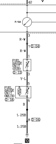
The fuel senders in these cars (and Evos) are indeed in series. There's an image posted here from the Evo wiring diagram and I have a Legnum one also here which shows them in series.
I'm not touching or going near the low fuel lights - I'm leaving those totally alone but I am curious where people expect the needle to be pointing when that light comes on, which is something I probably will be able to control as the light comes on at I think 10-12 litres left or thereabouts. As I'll be calibrating the needle to remaining fuel in the tank, this is achievable.
As for the resistors/rheostats, I'll be creating my own connection to both ends of it for the Arduino's voltage divider and monitoring circuit, and it will be cut out of the car's circuit (aside from DC ground of course). The only interface to the car's DC power system will be the MOSFET - and yeah unfortunately we're resorting to PWM driving the MOSFET at the moment to see how we go. Thanks for the guidance on the location of the resistor though; it was an afterthought to the diagram because I realised I had forgotten it completely.
I recently deployed an Arduino as an interface between my Evo X steering wheel buttons and my aftermarket cruise control. For the Arduino and such small power consumption I use a 7805 linear regulator coupled with a 0.33uF capacitor on the 12V side and a 0.1uF capacitor on the 5v side for smoothing. I didn't include all of that extra detail here as it would just deter from the concept of how to fudge the gauge.
Kaldek
2 AYC Bars
- Location
- Melbourne
- First Name
- Ed
- Drive
- 2000 Legnum VR4 Manual, Ford Territory family runabout, BMW K1300R.
- Thread starter
- #73
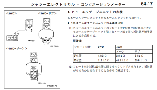
@Tony_T I'm also not sure if you can read Japanese but the following image from the service manual shows the resistance of each of the rheostats in the tank. Note that the totals of the two 4WD senders is about the same as the single sensor from the 2WD car. This all ties back to some Mitsubishi parts bin and "that'll be good enough" effort.
Tony_T
Leaving Skid Marks
Very interesting. The sender units I've had apart haven't had two resistance elements and the connectors look different so maybe there was a change sometime. No I can't read Japanese but that info is easy to understand without.
Anyway in almost every car nowadays the gauge is fed from a 10 volt or thereabouts regulator on the instrument cluster to prevent the reading changing as the 12 volt supply varies, you should keep that connection and could feed your board from that regulator too which will give you some transient protection.
I don't even know if the low fuel light in my current Legnum works, I've never dared to let the fuel get low enough to test it, I do know the one in my last Legnum worked though.
I think the bad non-linearity really results from the very unusual shape of the tank itself and with the inevitable variation of individual senders I'd expect your board will need calibration in the code for every combination of tank and sender so probably not a generally marketable product.
Why not leave the sender unit as original with the end earthed? You can surely rework the code for falling voltage with increasing fuel level, otherwise use an LM358 op amp to invert the signal (and amplify if wished); they're very small and inexpensive and being double you could use the second section to amplify feedback so allowing a lower resistor in the MOSFET source.
Anyway I'll shut up and let you get on with it.
Kaldek
2 AYC Bars
- Location
- Melbourne
- First Name
- Ed
- Drive
- 2000 Legnum VR4 Manual, Ford Territory family runabout, BMW K1300R.
- Thread starter
- #75
No need to shut up, this is actually helpful.I think the bad non-linearity really results from the very unusual shape of the tank itself and with the inevitable variation of individual senders I'd expect your board will need calibration in the code for every combination of tank and sender so probably not a generally marketable product.
Why not leave the sender unit as original with the end earthed? You can surely rework the code for falling voltage with increasing fuel level, otherwise use an LM358 op amp to invert the signal (and amplify if wished); they're very small and inexpensive and being double you could use the second section to amplify feedback so allowing a lower resistor in the MOSFET source.
Anyway I'll shut up and let you get on with it.
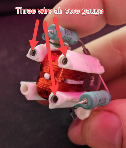
The gauge is a 3-pin air core gauge so it must be driven by an IC as the gauge needs a sine/cosine signal to each coil so that the magnetic field attracts the permanent magnet in the centre to align the needle in the desired direction. The question will be how that IC is measuring the tank level based on the change in resistance from the rheostats - current based or voltage based? I had a spare cluster board which I literally just tossed out (typical). I really need to just get off my ass and do some measurement, however I'm also waiting on delivery of a full set of all of the VR4 wiring diagrams for the entire production run which is about 4 manuals and it cost me a ton of money to get them from Japan. They'll also help fill out the missing stuff.
As for the inconsistency between cars, the accuracy doesn't have to be awesome - every VR4 shows half a tank as 1/3rd on the gauge and that's basically the only real change in accuracy we're really looking for ; all the extra measurements are just data that I probably don't need to use.
Tony_T
Leaving Skid Marks
Yes I must admit I've never investigated the gauge cluster itself but you do know that whatever IC drives that gauge simply looks for a variable resistance to ground. You don't really need to know any more because you can make a variable resistance from a MOSFET operating in linear mode if you do have a current sense resistor in its source and feed that voltage across the resistor back to maintain it, again an LM358 op amp could be useful since the voltage across the resistor would be small and you could make the op-amp / MOSFET combination simply a buffer driven by an analogue output from your chip, this would also overcome the approx. 2.5 volts gate threshold voltage (logic level MOSFET) so your chip's output could start at close to zero volts, wouldn't be exactly zero though as the original sender still has a finite resistance even at 'empty'. You really do need a real cluster on your bench to do measurements, and you need to take resistance measurements on the sender at frequent levels between empty and full to get some idea of what correction curve to apply. I wouldn't want to do that on a working car in case gunk from the bottom of the tank got into the fuel system; can you get a tank and sender combination from a wrecker or someone here on the forum in the interest of science? You'd only need to borrow it for a short time.
Now if you can cure the VR-4's affinity with petrol stations you will have achieved something, however I don't think the gauge has anything to do with that, they're just fuel hungry beasts by nature. Speaking of which mine's showing quarter tank so soon I'll be making that visit again, there goes probably about $70.
I'd love to see some of those diagrams, but I appreciate the expenditure on your part.
Kaldek
2 AYC Bars
- Location
- Melbourne
- First Name
- Ed
- Drive
- 2000 Legnum VR4 Manual, Ford Territory family runabout, BMW K1300R.
- Thread starter
- #77
Right, I've at least completed some wiring tracing and confirmed some stuff. I don't have all of the wiring diagrams, but I can confirm the following:
No this does not mean I am going to abandon my project just because I already can use the UTCOMP.
I bridged the yellow/purple and black wires on connector E12 with a 51 ohm resistor which brought the dash gauge up to - oddly enough - exactly where I reckon it should actually be for 25 litres remaining (halfway between 1/2 and /14 tank).
Now to go put some other resistor values across the pins for additional confirmation. I wonder now if the air core gauge I had lying around was actually from a Magna or something. Seems odd to use unregulated 12 volts if it was an IC controlling the gauge?
- Connector E12 is the connector where the fuel tank equipment interfaces with the dash cluster. It's a 10 pin connector under the rear seat, very close to the door.
- The Yellow/Purple (Violet) wire is the feed from the cluster
- The black wire next to the yellow/purple wire is the connection to signal ground.
- The power feed from the cluster (on the yellow/purple wire) is unregulated 12 volts from the car's IGN circuit.
- The yellow purple wire goes from connector E12 through to the secondary fuel level sender, and returns on a yellow/black wire to connector E-20 which is plugged directly into the fuel pump/sender assembly on the passenger side of the car (under the rear seats)
No this does not mean I am going to abandon my project just because I already can use the UTCOMP.
I bridged the yellow/purple and black wires on connector E12 with a 51 ohm resistor which brought the dash gauge up to - oddly enough - exactly where I reckon it should actually be for 25 litres remaining (halfway between 1/2 and /14 tank).
Now to go put some other resistor values across the pins for additional confirmation. I wonder now if the air core gauge I had lying around was actually from a Magna or something. Seems odd to use unregulated 12 volts if it was an IC controlling the gauge?
Kaldek
2 AYC Bars
- Location
- Melbourne
- First Name
- Ed
- Drive
- 2000 Legnum VR4 Manual, Ford Territory family runabout, BMW K1300R.
- Thread starter
- #79
you can make a variable resistance from a MOSFET operating in linear mode if you do have a current sense resistor in its source and feed that voltage across the resistor back to maintain it
I'm not quite clear on what you mean here beyond the use of a FET as a VCR. Particularly the text in bold isn't clear what you mean.
again an LM358 op amp could be useful since the voltage across the resistor would be small and you could make the op-amp / MOSFET combination simply a buffer driven by an analogue output from your chip, this would also overcome the approx. 2.5 volts gate threshold voltage (logic level MOSFET) so your chip's output could start at close to zero volts
If I was to drive a FET in the linear "ohmic range" I plan to use an Arduino coupled with an MCP 4901 (8-bit) DAC in order to generate voltages between 0 and 5 volts to drive the FET. I'm not clear on why I need the op-amp if the FET starts to act as a resistor around 2.5 volts and turns into a switch at 5 volts? Currently I have a STP16NF06L sitting on my desk whose stats I'm looking at.
Some current measurements taken today (as measured with a current clamp):
- Unloaded/open circuit voltage: 12.72 volts (Key On, Engine Off with battery on a charger)
- Circuit current with 72 ohms resistance (via the in-tank rheostats): 78mA
- Circuit current 4.9 ohms (via 4R7 resistor): 101mA
Tony_T
Leaving Skid Marks
You're making some great progress.
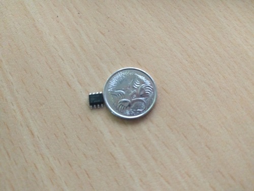
You will need the op-amp in a feedback loop to compensate for the FET's Vgs on threshold which will vary with individual samples and with environmental factors. If you feed your DAC into the non-inverting input of an op-amp, maybe through a bit of a resistive divider, have a resistor in the source of the MOSFET (maybe 3.9 or 4.3 ohms to allow a bit of spare over your 4.7 ohms for FSD) and connect the inverting input of the op-amp to the junction of the resistor and the source (maybe via a small RF stopper resistor say 1k ohm) you will have a circuit which follows your analogue signal without any dependence on the MOSFET's characteristics. By choosing the source resistor appropriately you can set up the value of current you want related to the analogue voltage, and you now have actual values for that. Your FET will start conducting at about 2.5 volts give or take, but will turn on fully very soon after (refer to the published specs on that MOSFET but remember they are subject to very wide spreads) so by the use of a feedback circuit you can cope with that. LM358's are ideal for such setups as the inputs can go to ground unlike many other op-amps and the output can swing almost the full supply voltage range which is much better than many. They're also low in power consumption and fully internally compensated for unity gain so no external compensation components are needed. A nice 8 pin DIL so easy to lay out on a PCB, either through hole or SMD. You could simply feed back the source voltage to an analogue input if your chip has one and do the FET compensation in code, but that sounds very difficult to me.
Alternatively you could do local PWM so the FET would be purely switching and have an inductor / capacitor filter in the drain circuit with a high speed diode to catch the inductor's flyback to convert the PWM back to an analogue current, this network would suppress any radiated interference too.
Similar threads
- Replies
- 10
- Views
- 398
- Replies
- 1
- Views
- 766

