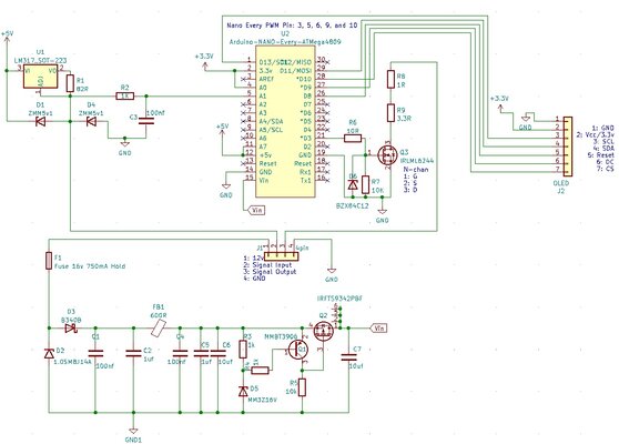
Fuel gauge recalibrator project

BCX

Administrator
Moderator
Location
SA
First Name
Bill
Drive
2000 Galant Type-V
1997 MK Triton GLS [6G74 conversion]
2019 i30 N-Line
I was actually asking for another project but thought it was relevant here. But its good to understand this stuff!

Is the zener after the current limiting resistor a valid design if the signal we wish to measure was the output of a 0-5v sensor such as oil pressure?

So no lm317, but sensors powered from same regulated rail as the mcu.
 

Tony_T

Leaving Skid Marks
Location
Hamilton New Zealand
First Name
Tony
Drive
Legnum VR-4 1997
OK fine about other uses.
If your analogue signal spans the entire 0-5v the zener may be a problem due to some leakage as the input approaches the 5v1 zener voltage. Unfortunately zeners don't have a perfect step response (no current until Vz and full current after Vz) so in that case the two standard diodes, one to ground to shunt negative inputs and one to +5v to shunt voltages above 5v is the way to go, remembering the approx 0.6 volt threshold for silicon diodes BUT unless there is a bit of series resistance before the diodes e.g the 1k spoken about earlier the 5 volt line must be fairly 'stiff' otherwise positive over voltages will be conducted to the 5v line and possibly damage other components. In the current project the input never goes anywhere near the 5 volt level so the zener will be fine. For the other application(s) just consider how close to 5v the signal will go and choose between the options accordingly, your ADC input probably won't go quite all the way to 5v anyway, there's only so many 1's it can output.

You might just scrape in with the LM317 but repeatability could be an issue. As your 5 volts is already well regulated you shouldn't have any issue with stability although the current drawn will be greater as 100 ohms when the sender is at minimum resistance will draw 50 mA dropping to about 25 mA at the 107 ohms end. You could decrease this by increasing the 100 ohms to say 220 ohms which will limit your voltage span to the same as with the LM317 (1.63v) where 100 ohms gives you a span of 2.58v for your analogue input.
 

Tony_T

Leaving Skid Marks
Location
Hamilton New Zealand
First Name
Tony
Drive
Legnum VR-4 1997
Just adding to that, I spent a bit of time searching constant current sources which could replace the LM317 and so get the advantage of linear slope, the only thing available that seems to be a likely candidate is the LT3092 which can work down to 1.2 volts across it. Data sheet:
Needs two resistors with it to set the current.
 

BCX

Administrator
Moderator
Location
SA
First Name
Bill
Drive
2000 Galant Type-V
1997 MK Triton GLS [6G74 conversion]
2019 i30 N-Line
Playing with some of this stuff on a breadboard.

Series resistor (1k) and two diodes in reverse between ground and rail seems to be ideal (i was using 1n4004)

Feeding in 15v:
  • Did not see 5v rail increase substantially (0.01-0.02v increase above 5v)
  • Current at 15v through 1k resistor was about 8mA measured through my lab powersupply.
  • Therefore series resistor dissipates ~120mW
  • ADC input saw just shy of 5.5v
  • Allows the full 0-5v input
The zener in reverse to ground after the series resistor doesnt allow the full 0-5v input (limited to about ~4.6v) as @Tony_T mentioned due to zener not being perfect.

The zener in reverse to ground before the series resistor will let the magic smoke out if accidently wired to 12v.

Now to test in vehicle...

Hope this helps.
 
Last edited:

Tony_T

Leaving Skid Marks
Location
Hamilton New Zealand
First Name
Tony
Drive
Legnum VR-4 1997
1N4004 diodes are a bit physically large and their current rating is not needed here, use 1N4148 / 1N914 or one of the thousands of equivalents which you'll readily get in a nice small SMD form for an easier fit on your PCB. There are even some (SOT23 package) twin diodes available in the correct configuration which would possibly make your layout even simpler. Since your ADC input is very high resistance you could increase the 1k to reduce the fault condition dissipation further, this would allow you to use a physically smaller resistor.
That zener leakage you observed would very likely be quite temperature dependent too. Best avoided for your other possible inputs.
I think you're getting very close to an ideal setup now.
 

kc427

Leaving Skid Marks
Lifetime Member
Location
HK
First Name
KC
Drive
VR4
@BCX, @Tony_T, thanks for the confirmation about the input section. It seems that it is ideal to be used then.

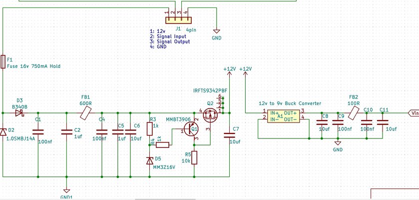
I have also revised the power supply section, ie, adding some protection and filtering. Also, I am still thinking whether using a buck converter to convert, eg, 12v to 9v is good idea or not. There are lots of buck converters that are very tiny and ready to be used.

Since I am not an EE guy, so I just take references from internet, please feel free to give any comment on the circuit.

Buck Converter.jpg
Power filtering 01.jpg
 

professor_jonny

Idling at the Lights
Location
New Zealand
First Name
Jonathan
Drive
Mitisuibishi 1998 RVR X3 auto rallysport
I just found this project and I am intrested as in my RVR the tank from half way seems to empty quicker than the top half and the span and zero is not accurate.

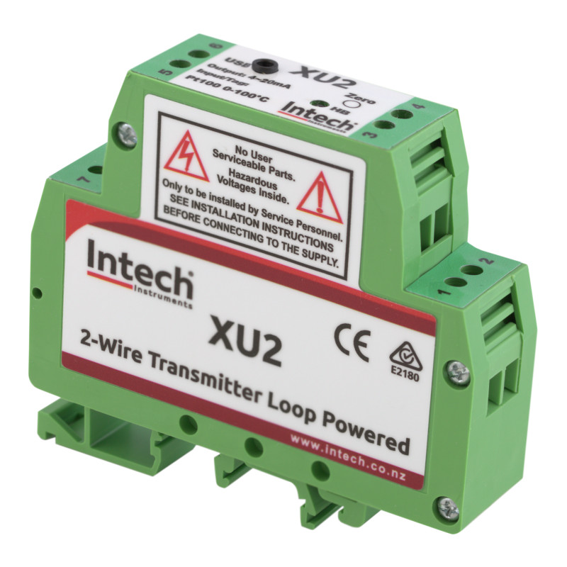
I work in the automation feild and I was looking at using a universal transmitter to rescale the signal back from the sender and this is what i was looking at as I use these for work and have a graph you can scale the output from the input based on a 32 point table.

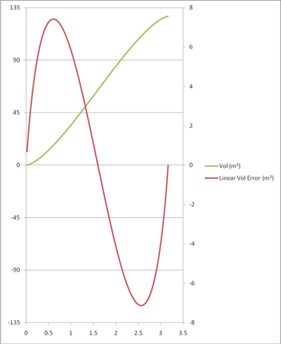
We use these to scale milk silos to give you a linear storage output as you can imagine a milk silo on its side looks something like below but if you raise one end the math calc gets out of hand expecially with floating poit math in a plc and this is where a custom scaling table makes thinsg easy.
silo level.png


your project seems to go along the same lines but what we do is fill the tank with a constant flow rate and calabrate it by logging the feed back from the tank real time between empty and fill and poke that in a table in the pressure transmitter back to the scada system.

Coult you not just fill the tank with a constant flow rate and calabrate it by logging the voltage feed back from the fuel sender in real time between empty and fill as we do? you could just have a pot and a simple button to scale the botom and top point of the needle with a simple calabraion procedure so it would be a universal product that may suit many vehicles?

I know my car sender says empty and it has reserve until the needle even moves and when you hit the top it still accepts fuel in the tank but it has hit the end of the scale so I was looking to modify my sender with a longer arm and bend it down a little bit to get a better span and zero then re cal the output better and this project would be awesome.
 

professor_jonny

Idling at the Lights
Location
New Zealand
First Name
Jonathan
Drive
Mitisuibishi 1998 RVR X3 auto rallysport
I have also revised the power supply section, ie, adding some protection and filtering. Also, I am still thinking whether using a buck converter to convert, eg, 12v to 9v is good idea or not.

Would this just be complicating the project a voltage reg would do?, sure it would save power but is this of consern in this project ? there are a few drop in replacment pin compatable 78xx style smps modules but it would be chaper to plce this on your own PCB.
is there a scemmatic for this project?
I dont fully understand what the 9v supply is for is this for the micro controller? can you not use the 5v of the ecu in the car?

I have done a project for the Xbox using a picaxe just cause it is easy to program for the public without dedicated hardware to program all you need is a simple circuit to wire to a 232 port on your pc.
 

Tony_T

Leaving Skid Marks
Location
Hamilton New Zealand
First Name
Tony
Drive
Legnum VR-4 1997
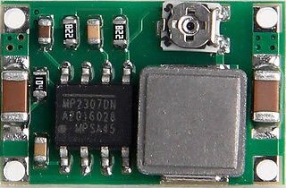
What I don't like about the readily available buck converters:
1. They often draw rather a lot of current just operating their driver IC so unless they're used for large output currents they are very inefficient. A good low dropout linear regulator good for plenty of current for an application like this will have only a very small quiescent current. I was going to suggest the LM2940 series (same package and pinout as 78xx series but much lower dropout) but I think there are even better ones out there now.
2. They are rarely if ever RF screened and filtered, e.g. the picture above. While that won't affect the use for the project, it may be a nuisance to any radio equipment that is fitted due to radiation of harmonics of the switching frequency.

Where did the 9 volts come into it?
That input protection circuit in post #186 above is extremely elaborate, way more than you need here. Refer back to my comments in post #156, that is really all you'd need.

@professor_jonny so the RVR has a somewhat similar problem. Is the fuel tank as weirdly shaped as our Legnum / Galant one is?
In theory the 5 volt supply from the ECU could probably be used if it can supply enough extra current, but one of the ideas of this project is to keep it simple to install and having to find a connection to get that 5v supply would complicate things compared to just picking up a 12v feed, a ground and splicing inline with the fuel sender.
 

professor_jonny

Idling at the Lights
Location
New Zealand
First Name
Jonathan
Drive
Mitisuibishi 1998 RVR X3 auto rallysport
@professor_jonny so the RVR has a somewhat similar problem. Is the fuel tank as weirdly shaped as our Legnum / Galant one is?
In theory the 5 volt supply from the ECU could probably be used if it can supply enough extra current, but one of the ideas of this project is to keep it simple to install and having to find a connection to get that 5v supply would complicate things compared to just picking up a 12v feed, a ground and splicing inline with the fuel sender.

Yes I think this is a more common problem than you think as my wife said the same on her previous car and I think a project like this could possibly benifit other vehicles.
The tank in my RVR is to some extent shaped a bit odd nut nothing really abnormal I guess from the ones I have seen but the output is non linear.
I can do 250 km from fill to half empty and only get 150km from half fill to empty but I have never really dared to see how far it will go after the light comes on (yet).


I have also seen this issue of fuel senders mis reporting on diesel generators we have imported from overseas being mis matched with the guages fitted to them but that was just a china quality control issue.

I do know my brother fitted saddle tank setup to his classic mini where it has a tank in place of the wheel that sits flat in the boot piped to the normal tank you can imagine it shaped like a gumboot and as you can imaging the output is severly non linear.

If you could measure and log while filling from the pertol station as it is a constant flow rate from the gear pumps in the bowser.
You know how much you have put in over what time as you can log the results as it is filling from the time it started to rise until it stops on top level.

An esp32 with built in wifi you could punch in the data on the display of the pertol bowser from your phone and scale the output to be acurate just from a single fill of your car at the pertol station.

On a tangent to this but still car related....
I have looked at another project recently to do with older cars with a single coil pack to convert them to a multi coil setup.

The plan was to make up a circuitboard to drive multiple coil packs from a single distributor or ecu output as I am aware no such device exists.

The plan was to select the correct spark plug from the distributor's hall sensor and use the ecu's ignitor signal or the distributor pickup to fire the spark plug selected by the box this way you could convert a car to multi coil pack with out replacing the ecu many cars could benifit from this.

my other car is a 4age and the factory spark setup dies at high rpm (6.5k+rpm) and would benifit from individual coilpacks but it would require an ecu swap to do.

I was going to try bang up something but im not fimular with the likes of protecting stuff from flyback in thousands of volt coilpacks an mounting such a device ontop of an engine block as it is a harsh area.
I probally should start up a thread somewhere about this somewhere to see what people think good idea or not.
 

Tony_T

Leaving Skid Marks
Location
Hamilton New Zealand
First Name
Tony
Drive
Legnum VR-4 1997
Interesting thoughts, as you say maybe another thread for that. BTW the primary of an ignition coil generally reaches only about 400 to 500 volts unless the secondary is disconnected, ignition units will have a clamping circuit to prevent it going higher so modern MOSFETs are likely to be satisfactory for the switching. You would need more hall sensors (maybe only one) in the distributor as an indexer to tell your system which spark plug to fire in relation to the pulses from the existing one which fires for every cylinder. Going a bit OT though.
 

kc427

Leaving Skid Marks
Lifetime Member
Location
HK
First Name
KC
Drive
VR4
What I don't like about the readily available buck converters:
1. They often draw rather a lot of current just operating their driver IC so unless they're used for large output currents they are very inefficient. A good low dropout linear regulator good for plenty of current for an application like this will have only a very small quiescent current. I was going to suggest the LM2940 series (same package and pinout as 78xx series but much lower dropout) but I think there are even better ones out there now.
2. They are rarely if ever RF screened and filtered, e.g. the picture above. While that won't affect the use for the project, it may be a nuisance to any radio equipment that is fitted due to radiation of harmonics of the switching frequency.

Where did the 9 volts come into it?
That input protection circuit in post #186 above is extremely elaborate, way more than you need here. Refer back to my comments in post #156, that is really all you'd need.

@professor_jonny so the RVR has a somewhat similar problem. Is the fuel tank as weirdly shaped as our Legnum / Galant one is?
In theory the 5 volt supply from the ECU could probably be used if it can supply enough extra current, but one of the ideas of this project is to keep it simple to install and having to find a connection to get that 5v supply would complicate things compared to just picking up a 12v feed, a ground and splicing inline with the fuel sender.

Understand. Because I only know one of the pros about buck converter is it consumes less current itself and produces less heat so no need the heat sink or copper filling on PCB and it makes the PCB and the whole thing smaller and can hide somewhere behind the dash without any air cooling place. But yes, can remove the buck converter and feed the clean 12v into the Arduino directly.

The 9 volt originally used if using buck converter. So, if removing the buck converter, no need to worry about that.
 

kc427

Leaving Skid Marks
Lifetime Member
Location
HK
First Name
KC
Drive
VR4
Would this just be complicating the project a voltage reg would do?, sure it would save power but is this of consern in this project ? there are a few drop in replacment pin compatable 78xx style smps modules but it would be chaper to plce this on your own PCB.
is there a scemmatic for this project?
I dont fully understand what the 9v supply is for is this for the micro controller? can you not use the 5v of the ecu in the car?

I have done a project for the Xbox using a picaxe just cause it is easy to program for the public without dedicated hardware to program all you need is a simple circuit to wire to a 232 port on your pc.
I have posted the schematic on post #142 already. That is very simply and no protection at all, so if you want simply circuit and no worry about the Arduino, you can use it for the program. Please note that it is not yet test at all, so risk on your own.
 

kc427

Leaving Skid Marks
Lifetime Member
Location
HK
First Name
KC
Drive
VR4
Ok, thank for others comments, revised the circuit by adding the protections. Please be noted that nothing is tested yet, so risk on your own.


Schematic v1.1 :-

schematic_v1.1.jpg
 

kc427

Leaving Skid Marks
Lifetime Member
Location
HK
First Name
KC
Drive
VR4
@Tony_T , just another question, as you know, the LM317 is good for 5v input. If using 3.3v, what is the alternative device I can use? The reason why I ask is personally, I am thinking to use ESP32 instead of the Arduino Nano Every because of the much lower price, but the ESP32 is based on 3.3v for those input/output pins and also the analog input pins.
 
Last edited:

professor_jonny

Idling at the Lights
Location
New Zealand
First Name
Jonathan
Drive
Mitisuibishi 1998 RVR X3 auto rallysport
@Tony_T , just another question, as you know, the LM317 is good for 5v input. If using 3.3v, what is the alternative device I can use? The reason why I ask is personally, I am thinking to use ESP32 instead of the Arduino Nano Every because of the much lower price, but the ESP32 is based on 3.3v for those input/output pins and also the analog input pins.
LT1763 ?
You could also use a MC78LCxx and put a few series diodes to drop supply to the 12v max input ?
 

kc427

Leaving Skid Marks
Lifetime Member
Location
HK
First Name
KC
Drive
VR4
@BCX , @Tony_T when you talking about protecting the input pin by adding diode, resistor and capacitor, is this drawing enough for the protection? Just a gentle reminder that the fuel sender is just a rheostat with low resistance, around 4-107 ohm only, which is connected to the GND as in the drawing, and simply using the Arduino to read small resistance.

@Tony_T , just want to double check, for the input signal(post #167), should I use Zener diode or just normal ordinary diode for the power rail and the ground? Are the direction correct? thanks.
 

kc427

Leaving Skid Marks
Lifetime Member
Location
HK
First Name
KC
Drive
VR4
LT1763 ?
You could also use a MC78LCxx and put a few series diodes to drop supply to the 12v max input ?
If the LT1763, it could be a quite expensive component to be used, and need to consider carefully if using
 

Tony_T

Leaving Skid Marks
Location
Hamilton New Zealand
First Name
Tony
Drive
Legnum VR-4 1997
Let me go through some things with the intention now of using a 3.3 volt supply, sorry I don't have that nice schematic package you've used or I'd draw it:
1. That output MOSFET you've chosen has an absolute max gate to source voltage rating of 12 volts so I'd suggest reducing your zener D6 to a 10 volt one. Increase R6 to 1k and R7 to 47k (neither value at all critical), this will give your micro more protection against capacitively coupled transients and also remove some harmonics from the PWM signal.
2. D1 is redundant, omit it.
3. LM317 as discussed is barely adequate for a 5 volt supply, I really suggest staying with just a 100 ohm resistor to the 5 volts, the input to the ADC won't be a linear voltage / sender resistence curve but sender resistance surely won't be linear with fuel level so there is no advantage, you'll still have to do a fuel level / voltage calibration curve and use that for your PWM control.
4. If you keep to a 100 ohm resistor you don't then need or want D4 either, what you should do is connect a diode from A1 to ground, (cathode to A1) and another diode from A1 to +3.3v, (anode to A1), as I suggested use one of the twin diode SOT23 packages which come in that exact configuration.
5. You may just as easily feed the 100 ohm from the 3.3v supply, this will reduce the current at full tank and will allow a span of just over half of the 3.3v at your ADC input. If you need more span you could connect a single supply op-amp as a gain buffer between the protection I've just described and the ADC input, feed its supply from the 3.3v also. Do you need 5 volts for anything at all then? I see it fed into the micro too at pins 11 & 12, can't that just be 3.3v?
6. For power supply protection I'd just use a fuse (could even be a self resetting type) followed by a standard diode (1N400x series) into a small inductor (a few hundred µH with fairly low DC resistance). Follow that by a 0.1µF capacitor to ground, a 100µF electrolytic also to ground and a TVS diode good for say 18 volts also to ground (as some alternators will go over 15 volts). This will all feed into your micro board (presumably the 3.3v regulator is on that board?).
Sorry I'm not familiar with either of those processor boards you mention so I'm not sure what is actually present on them.

OK that's enough of another wall of text for now. Back to you!
 

kc427

Leaving Skid Marks
Lifetime Member
Location
HK
First Name
KC
Drive
VR4
Let me go through some things with the intention now of using a 3.3 volt supply, sorry I don't have that nice schematic package you've used or I'd draw it:
1. That output MOSFET you've chosen has an absolute max gate to source voltage rating of 12 volts so I'd suggest reducing your zener D6 to a 10 volt one. Increase R6 to 1k and R7 to 47k (neither value at all critical), this will give your micro more protection against capacitively coupled transients and also remove some harmonics from the PWM signal.
2. D1 is redundant, omit it.
3. LM317 as discussed is barely adequate for a 5 volt supply, I really suggest staying with just a 100 ohm resistor to the 5 volts, the input to the ADC won't be a linear voltage / sender resistence curve but sender resistance surely won't be linear with fuel level so there is no advantage, you'll still have to do a fuel level / voltage calibration curve and use that for your PWM control.
4. If you keep to a 100 ohm resistor you don't then need or want D4 either, what you should do is connect a diode from A1 to ground, (cathode to A1) and another diode from A1 to +3.3v, (anode to A1), as I suggested use one of the twin diode SOT23 packages which come in that exact configuration.
5. You may just as easily feed the 100 ohm from the 3.3v supply, this will reduce the current at full tank and will allow a span of just over half of the 3.3v at your ADC input. If you need more span you could connect a single supply op-amp as a gain buffer between the protection I've just described and the ADC input, feed its supply from the 3.3v also. Do you need 5 volts for anything at all then? I see it fed into the micro too at pins 11 & 12, can't that just be 3.3v?
6. For power supply protection I'd just use a fuse (could even be a self resetting type) followed by a standard diode (1N400x series) into a small inductor (a few hundred µH with fairly low DC resistance). Follow that by a 0.1µF capacitor to ground, a 100µF electrolytic also to ground and a TVS diode good for say 18 volts also to ground (as some alternators will go over 15 volts). This will all feed into your micro board (presumably the 3.3v regulator is on that board?).
Sorry I'm not familiar with either of those processor boards you mention so I'm not sure what is actually present on them.

OK that's enough of another wall of text for now. Back to you!
Thanks a lot for you explanation. I learn a lot from that. I will take all as a notice first as the schematic in the previous post is more or less a suitable one to be used, and anyone can use it and feel free to modify if needs. After I finalize this circuit for myself, I will find a way to log the ADC voltage vs the true resistance of the fuel sender, or ADC voltage vs fuel litre used. One of the way may be using a well-known "MPGuino" which seems to be quite accurate to calculate fuel consumption/usage. However, there are a lot to different "MPGuino" variants around with many different features added, so I need to find a suitable simple one so that I can log the fuel usage vs the ADC voltage. Anyway, it's the next plan.

BTW, the schematic I drew is actually from a website, https://www.falstad.com/circuit/, which is quite good to do simulation, and free to use.
 
Top Bottom