UTCOMP installation

Grid

Leaving Skid Marks
Location
Poland
First Name
Tomasz
Drive
Legnum 6A13TT, Galant 6A13
Tomasz... did you use the clock's standard board for the buttons? Just resoldered your own 3 wires? or is that the one supplied with the kit?

Exactly, I used the stock buttons, took off the original wires and soldered in a new set of leads connecting to the relevant UTComp inputs (button inputs).

Also the now unneeded clock harness is very useful as it contains power, ignition and lights-on signals that you can use. Just use a multimeter to find out what is what (simple rule to follow, GND of multimeter always goes to a ground point on the car, never measure between two random wires).
 

trotty

3 AYC Bars
Location
nsw
First Name
Daniel Trotman
Drive
2000 vr4 Legnum 5 sp man
2006 Suzuki Swift Sport 5 sp man
Just ordered
Mine. Just got the blue display. Didn't bother with the oled
 

Blackbird

Leaving Skid Marks
Premium Member
Location
NSW
First Name
Steve
Drive
2001 ADM Evo 6.5 Makinen Edition,
2001 Legnum VR-4 Type S Written off,
2000 Legnum VR-4 Type S Manual with 23,489km!!
Just ordered
Mine. Just got the blue display. Didn't bother with the oled
You buckled hey lol.... welcome to my life!! hahahaha
nice one mate!! looks to be a really great addition to our cars!
 

Blackbird

Leaving Skid Marks
Premium Member
Location
NSW
First Name
Steve
Drive
2001 ADM Evo 6.5 Makinen Edition,
2001 Legnum VR-4 Type S Written off,
2000 Legnum VR-4 Type S Manual with 23,489km!!
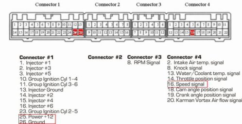
Don't feed it 5 volts - just tap its signal wire. It's the Yellow-Green wire (pin #13) on the driver's side connector to the ECU, which is also called "C39" - in other words, C39 and pin #13. The UTCOMP has 0-5 volt inputs you can use.

Here's what the UTCOMP manufacturer says about calibration:
http://www.reveltronics.com/forum/viewtopic.php?t=58

You need to download his Excel file, and then record the behaviour of the Legnum coolant sensor.
To do this on a Legnum, you would run EvoScan to get a live log of the coolant temp whilst measuring the voltage you're seeing on your tap wire with a multimeter. Start with a cold (at least overnight) engine. Connect all your stuff and start the car. For every 10 degrees C of temperature change as the engine warms up, record the voltage you see on the multimeter. Start measuring based on the coolant temp you're seeing right as the car is first started.

Then, punch that data into his Excel spreadsheet and take the A, t, and T0 values from that. Enter those into the UTCOMP application under Settings-->Advanced-->Temperatures (NTC).


P.S. I don't even own one of these yet but I've done this before on motorbike piggyback ECUs and it's the same process.
Thankyou for that Ed..

I got an email last night from Artur (the owner of the company) and said it's safe to piggy back the coolant temp sensor off the pinout of the ECU.. I have the diagram here and seeing what needs to be tapped off...damn international post!!! hahahaha
Thanks for your help mate... very appreciated :)
Steve
VR4ECUPinoutSpeedsensor-1.jpg
 

Kaldek

2 AYC Bars
Premium Member
Location
Melbourne
First Name
Ed
Drive
2000 Legnum VR4 Manual, Ford Territory family runabout, BMW K1300R.
I got an email last night from Artur (the owner of the company) and said it's safe to piggy back the coolant temp sensor off the pinout of the ECU.

Great! I assume he's tapping the ECU ground for the UTCOMP ground as it ensures a stable ground? The diagram also looks to be specific for speed sensor tapping, but I guess you'd already worked that out.
 

trotty

3 AYC Bars
Location
nsw
First Name
Daniel Trotman
Drive
2000 vr4 Legnum 5 sp man
2006 Suzuki Swift Sport 5 sp man
Would be awesome to be able to display intake temp, but being in the afm it's only reading air coming into the airbox. I want actual manifold air temp. Would be great to be able to display real time knock too. Ideally these will be priority.
Oil pressure
Oil temp
Boost/vacuum
Water temp
Battery voltage

With possibility of
Intake temp both post turbo and intake manifold. (For IC efficiency)
Exhaust gas temp OR o2 sensor.
 

Kaldek

2 AYC Bars
Premium Member
Location
Melbourne
First Name
Ed
Drive
2000 Legnum VR4 Manual, Ford Territory family runabout, BMW K1300R.
Would be awesome to be able to display intake temp, but being in the afm it's only reading air coming into the airbox. I want actual manifold air temp. Would be great to be able to display real time knock too. Ideally these will be priority.
Oil pressure
Oil temp
Boost/vacuum
Water temp
Battery voltage

With possibility of
Intake temp both post turbo and intake manifold. (For IC efficiency)
Exhaust gas temp OR o2 sensor.

Just buy some temp sensors and wire them in where you want them. I think the UTCOMP website even lists recommended parts for that.

As for knock, that's a calculation from the ECU based on a bunch of parameters, such as sensitivity based on engine rpm and airflow/load. Best option here is CEL-on-Knock option in your ROM. If you wanted a log of knock you're limited to EvoScan.
 

Blackbird

Leaving Skid Marks
Premium Member
Location
NSW
First Name
Steve
Drive
2001 ADM Evo 6.5 Makinen Edition,
2001 Legnum VR-4 Type S Written off,
2000 Legnum VR-4 Type S Manual with 23,489km!!
Great! I assume he's tapping the ECU ground for the UTCOMP ground as it ensures a stable ground? The diagram also looks to be specific for speed sensor tapping, but I guess you'd already worked that out.

It would appear so... i've asked a bunch of questions and he's been really helpful... yes all power will come from the ecu pins... fuse on the 12v input yes the speed sensor tapping is going from there too..
You do get two temp sensors but I think they'd be only suited for inside the cabin reading.. and outside reading..
 

Grid

Leaving Skid Marks
Location
Poland
First Name
Tomasz
Drive
Legnum 6A13TT, Galant 6A13
The temp sensors I got with my Pro are bare digital DS-type sensors. These require soldering of leads, and preferably should be put in some casing, shrink-wrapped, anything to protect them from humidity and condensation. I am planning to encase a couple in high-temp silicone and use them for inlet and outlet FMIC temp monitoring. If I manage a write-up will follow :)
 

Blackbird

Leaving Skid Marks
Premium Member
Location
NSW
First Name
Steve
Drive
2001 ADM Evo 6.5 Makinen Edition,
2001 Legnum VR-4 Type S Written off,
2000 Legnum VR-4 Type S Manual with 23,489km!!
Well.... it's been an interesting day and a half figuring this out... pulling it apart and putting it back together and programming..
Flat battery aside lol!

Note: coolant temp and boost sensor aren't connected yet... the pressure sensor for the boost part is on the way but I've added the wire for that already.. simple hook up..
The coolant.. haven't figured it out yet... pinout from the ecu doesn't show anything so it's either a stand-alone unit... or I'll try to tap to two wire temp sensor on the thermostat housing when I get a chance....

I adapted the standard clock's keypad to work with the UTCOMP... that way it fits perfectly in the stock clocks housing...
Note 2: when doing so.. the buttons aren't wired simply 1, 2, 3... it's more like 1, 3, 2... tracing the circuit board will clarify what I'm talking about... works perfectly though....

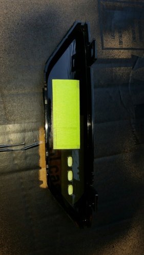
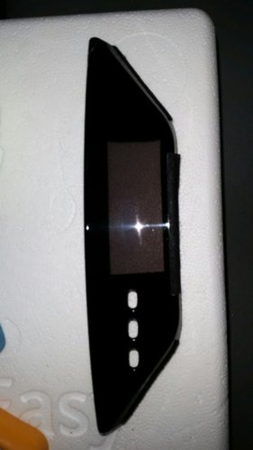
I removed the clocks inner black shroud.. (the bit that blacks out the surrounding part (apart from the screen) as it'll be a pain to trim to suit and chances are it'll look terrible.. so I masked up from the outside (yes outside) to get an outline on the UTCOMP's screen layout.. then masked inside the smoked outer clock screen and painted the inside...I used Black Plasti-dip... cos' I know I can remove it fairly easily if I need to.. (ala: just like painting a polycarbonate body on a R/C car....)
The clock without the black inner blanking shroud is see through.. so if you don't black it out you'll see into the depths of the dask and it looks unsightly when sunlight hit's it... also mask around as close as you can to the outer border of the UTCOMP's screen as it's backlit and will show spots of light around the border at night and that looks even worse...

The clock is a bitch to remove... best thing to do is use a paint tin opener and unclip the forward clips first (closest to the windscreen) then removing your stereo and aircon/heating controls... remove the center upper vents... two metal clips under that and it slides out.... then using long nose pliers (the longer the better) gently squeeze the two rear clips of the clock to pop it out otherwise you risk damaging the clock itself...

Take heed.... when programming.. and calibrating the speed.... the UTCOMP reads the Legnums speed at exactly half... meaning you'll be doing 60kph... but the UTCOMP will show 30kph... easy adjustment using the calibration assistant...

Also when doing a calibration for fuel consumption... do the first initial as per the instruction manual... fill her up to the very top... take it for a test drive.. 50-100km... and fill it up again exactly the same way (as I did.. same pump at the same servo with the same amount of clicks...) worked out to be 9.8 litres to 100km
I did about 65km on the M7.... the rest the Processor will work out... the longer the drive.. the more accurate the UTCOMP will be....

READ THE INSTRUCTIONS CAREFULLY!! they spell out in simple terms how to for everything and its a great idea to print them out and take with you!!! lol
trust me on this... especially when calibrating the thing to work properly.....

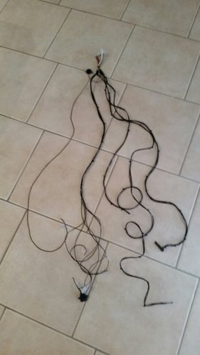
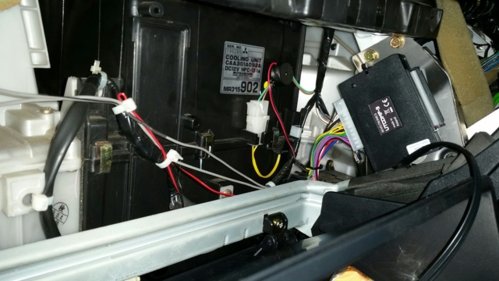
here are some pics of my harness which i made up... some masking and painting... and the final mount position where I installed the unit itself...
Remember you'll need to plug in a USB lead to program with a laptop..so mount it accordingly... don't mount it high up in the dash as you'll need to connect it to a usb cable and laptop to help with calibration and adjustment.......

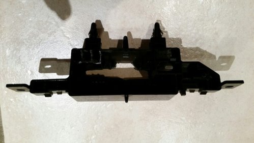
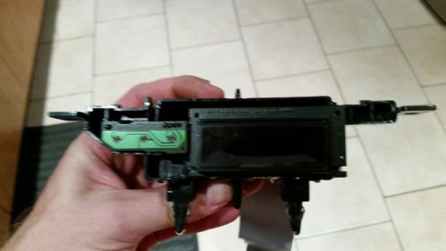
This is the UTCOMP 3... NOT the pro... the screen fits the standard clock without issue... though the rear shroud of the clock needs a hole slotted in the back for the ribbon cable and keypad harness... and a small bit of plastic trimmed to allow the screen to sit flat in the shroud... hot glue is what i used...
Also if you do this method... glue the standard key pad onto the keypads circuit board to stop it flopping about and becoming misaligned... two drops of glue on the little mounting spigots holds it well... any questions ask away...

it's pretty straight forward to where I'm at right now... instructions are great with this unit and pretty sure if I can do this... anyone can :)

Harness:


The backing shroud


the backing shroud post slottage.... note top left the plastic that was removed (the 3 hole looking thing) to allow the UTCOMP's screen to sit flush
Same as Tomasz..

Masking first on the outside with the screen fitted... then copied in reverse on the inside.. ready for painting


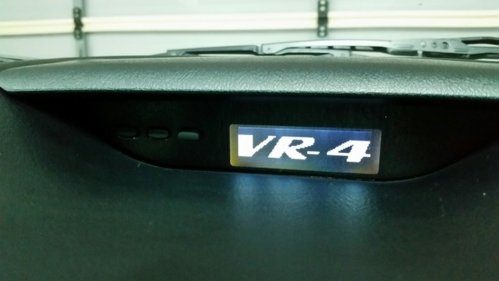
Finished product


Final mount position... glovebox unclipped and it's mounted (zipties) on the left of the stereo..


AND of course... the all important "welcome screen"!!! hahaha
20160220_222856_resized.jpg


As I said... anyone have any questions.. feel free to ask... and i'd like to say a big thankyou to everyone that's helped with this... Tomasz!! and Artur from UTCOMP... awesome work!!

Steve
 

Blackbird

Leaving Skid Marks
Premium Member
Location
NSW
First Name
Steve
Drive
2001 ADM Evo 6.5 Makinen Edition,
2001 Legnum VR-4 Type S Written off,
2000 Legnum VR-4 Type S Manual with 23,489km!!
I blacked out the outside of the screen... and the top of the stock keypad to stop reflection... not really needed if you paint the outer clear smoked screen....
Damn server issues... grrrrrrr


Blackbird

Leaving Skid Marks
Premium Member
Location
NSW
First Name
Steve
Drive
2001 ADM Evo 6.5 Makinen Edition,
2001 Legnum VR-4 Type S Written off,
2000 Legnum VR-4 Type S Manual with 23,489km!!
Nice work Dan...
What did do for the AFR and temp gauges?? stand alone or did you use what the car already has?
 

trotty

3 AYC Bars
Location
nsw
First Name
Daniel Trotman
Drive
2000 vr4 Legnum 5 sp man
2006 Suzuki Swift Sport 5 sp man
Afr isn't hooked up I'll need a sensor for that. Temp I ran off the ecu pin out. Plug 4 pin 13 coolant temp sensor
 

Blackbird

Leaving Skid Marks
Premium Member
Location
NSW
First Name
Steve
Drive
2001 ADM Evo 6.5 Makinen Edition,
2001 Legnum VR-4 Type S Written off,
2000 Legnum VR-4 Type S Manual with 23,489km!!
Oh ok.... bugger... I connected pin 13 of plug #4 and got nothing....hmmmm maybe I should try to get a proper connection again...lol

That's from pin... ATS from the UTCOMP plug yeah?? pin 20?
 

Blackbird

Leaving Skid Marks
Premium Member
Location
NSW
First Name
Steve
Drive
2001 ADM Evo 6.5 Makinen Edition,
2001 Legnum VR-4 Type S Written off,
2000 Legnum VR-4 Type S Manual with 23,489km!!
Durrrr... never mind me.... forgot to enable NTC-1 in advanced settings lol....

EDIT: and it's supposed to be connected to ADC1 or ADC2 had the spare wire I hooked up for the boost sensor worked with the stock temp sensor...swapped some settings and it all works well!!!

So I soldered in another wire for the boost sensor when it arrives.. :) happy days!!
Note to self.... drink less beer when installing stuff like this lol
 

trotty

3 AYC Bars
Location
nsw
First Name
Daniel Trotman
Drive
2000 vr4 Legnum 5 sp man
2006 Suzuki Swift Sport 5 sp man
Ahhhhh yeah that helps. Lol. And I had to enable oscilloscope on the o2 sensor input and engine coolant temp. I hooked my other spare input for headlights into the fan relay, that is also switchable. My car already beeps for headlights on. So nice to know when fans are on.
 

Blackbird

Leaving Skid Marks
Premium Member
Location
NSW
First Name
Steve
Drive
2001 ADM Evo 6.5 Makinen Edition,
2001 Legnum VR-4 Type S Written off,
2000 Legnum VR-4 Type S Manual with 23,489km!!
Well.. after a couple of weeks with some jiggary pokery... my fuel ecomomy is close... really close....
after some long drives and not so long drives and filling up at exactly the same pump and the same servo I'm about 0.2 litres per 100km out lol

car was showing 111.7 km trip.... UTcomp showing 13.7litres per 100... filled up 15.54 litres to the brim... using an online calculator...13.91km per 100

Speed and km you're best of using a GPS speed sensor... (I found that my VR-4's speedo is quite accurate (within 5kph at 100.....reading 105kph when reality was 100kph) near dead on at 60kph)

boost sensor was another story... after some swearing.. praying to the boost Gods and bench testing the boost pressure sensor multiple times with a voltmeter and gauged pump, I came to the conclusion that:

A) 1V equals atmospheric pressure (1 bar, approx 14.7psi on a standard day)
B) 0v equals 1 bar negative pressure (So when the car has acc on it (engine is off though) shows 0 psi...!!
C) 2V equals 2 bar pressure absolute.. so positive 14.7psi boost from the engine... since mine only runs about 13psi max.. it'll have to do...

NOTE: that's the sensor i purchased from a seller on ebay... and may not be the same as anyone elses... it's probably best used as a guide and would tune off it that's for sure but it seems accurate enough...
BTW..
Love the unit... totally awesome addition to the car... would recommend this mod to anyone!!!
 

ersanalamin

Leaving Skid Marks
Location
Indonesia
First Name
Ersan Al Amin
Drive
Year 2000 EA5A => FL EC5A
Guys I need some info equation for UTCOMP set up which are
1. Engine coolant sensor
2. EGT
3. SPeed Sensor

Anyboy tap Digin RPM to ECU IFS (RPM) Cable?
 

Kaldek

2 AYC Bars
Premium Member
Location
Melbourne
First Name
Ed
Drive
2000 Legnum VR4 Manual, Ford Territory family runabout, BMW K1300R.
For engine coolant, tap into pin #13 on ECU connector C39 and connect it to one of the Adc connectors on the UTComp. Set that connector to be temperature NTC-1 in the UTCOMP program. After that you need to calibrate it.

For fuel, tap into pin #1 on ECU connector C33 and connect it to pin A10 on the UTCOMP. Set the fuel consumption signal to be PWM - controlled by GND.

For speed, tap into pin #16 on ECU connector C39 and connect it to pin A22 on the UTCOMP. Calibration is also required.
 
Top Bottom